Sunday, June 26, 2011

A Brief Pause

Well, my schedule will be keeping me away from the boat project for most of the next month.  I had hoped that the boat would be finished and ready to try out by mid-July, but that's clearly not going to happen.  Let's take stock of where the project sits now:
  • 2 paddles ready for finish work, but I still need to start the second attempt at a steering paddle.
  • Hull panels cut out; some epoxy coating done, but less than half of the interior surface area has gotten its first of the recommended two coats so far.
  • Sail panels cut; stitching panels together about 1/3 of the way done.
  • A lot of timber collected, but I still need the outrigger float and 3 long, thin poles.
  • All materials and necessary tools purchased except for incidentals like rope, twine and paint.
 Recent car repairs have taken me away from boatbuilding, and I couldn't start filleting until the last of the materials arrived earlier this week.  So I have some good excuses - but I'm concerned that I won't get the chance to use the boat before this year's sailing season is over at this rate.

I'll post more news when I have time to make some. 

Saturday, June 18, 2011

Sailmaking

I slathered a layer of epoxy on the interior sides of some panels the other night, but the really big news here is that I've begun to make my sail.  I got the fabric today from Rockywoods, and by the end of the evening I'd measured and cut out the two halves of the sail.

The fabric (a 4-oz ripstop polyester) is attractive and lightweight.  One side is coated with a urethane treatment of some sort, so there's a slight color difference between the sides.  But appearance isn't high on my priority list, and anyway, it'll look way better than a blue tarp would have.

Squeezing 57 sqft of sail into 5 yards of fabric.
I rolled it out and followed the instructions in the plans for squeezing the entire sail into 5 yards of fabric.  (The plans discuss doing this with 6' wide fabric; my fabric was about 5' wide, but it fit.  Just barely....)

For a while, I was at a loss as to how to get the shape from the plans to the cloth.  The plans list the length of the curved head and foot of the sail, and they list the length of the center of the sail, but there was no list of offsets at various station lines like there had been for the plywood.  There was also some confusion as to how I could get the proper curve for the hollow at the open end of the crab claw.

I had learned in my navigation class how to use an engineer's scale to read a measurement from a nautical chart, and I had heard somewhere that you can do the same thing with boat plans.  So I got the engineer's rule from my nav gear and confirmed the width of the sail at the top, which allowed me to determine that the sail curves inwards one foot from the tips to the center.  Once I've joined the two halves, I'll draw that curve in with a batten.
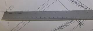
If you look closely at the full-sized version of this pic, you can see that the plans read 6'7" (or 79") along this line.  The plans are at 1:10 scale, and I've laid the 1:10 edge of my engineer's rule along the line.  This allows me the determine that the length shown is indeed 79".  It's unnecessary for this sort of situation, but this technique is useful if you want a dimension that's not given in the plans.  As long as your rule has a scale that matches the scale of your plans, it will work.

I decided the best way to get the shape of the long curve onto the cloth would be to carefully mark the three corners, then mark the length of the curved side on a batten, and then use exactly that much batten to draw in the curve.  My boys helped again - they're getting to be pro's after the plywood drafting job.

I soon had the shape of the two sail halves drawn in, but it would be a mistake to cut along those lines.   The center seam needs some overlap, and it takes fabric to enclose the rope that's supposed to strengthen each edge.  So I traced in a second line in a different color, 1.5" from the edge of the sail, and this is the line I cut.

When it was all done, I had two halves of a crabclaw sail.  I couldn't resist the temptation to lay them out together to get a sense of the full size of the thing.  At 57.5 sqft of sail area, it's a pretty powerful rig.  Setting it out in the living room brought that home a bit - it seems bigger than the sail for my El Toro dinghy, which weighs about the same.

Next up in sailmaking: I'll be pinning and stitching the center seam together.  I also need to procure some rope for the edges so I can sew those in.    I may also cut some reinforcement radius pieces for the corners out of my meager scrap pile.  It seems smart - most sails have reinforcement patches there.

Meanwhile, I still have interior epoxy coating to do.  Everything is supposed to get two coats, with a bit of sanding between.  And if I'm close to having a sail, I really ought to consider getting the spars finished.  Plenty to do!

Wednesday, June 15, 2011

Big Spender!

My tight budget finally reached the point where I was able to order the epoxy, fiberglass tape, and other specialty supplies needed to assemble the hull.  So today, I placed an order with Merton's  Fiberglass & Marine Supply for those materials.  Their prices were good, their website informative.  They don't do e-commerce, but they took my order over the phone (~$155) and promised to ship it out later in the afternoon. 

There were a few decisions to agonize over in this purchase.  First of all, what epoxy to use?  Since I was given some cast-off System3 epoxy, with mixing pumps, from a friend's Eastport Pram build, it seemed best to stick with that brand.  Next, what size?  The cost per unit drops steadily as the size of the container goes up.  The plans recommend (3) of the West System "A" size packs, which are about a quart each; Mertons' offered System3 in 0.75gal or 1.5gal sizes.  The bigger size was very tempting, especially because the smaller pack is probably not quite enough to build this boat.  But I still have a quart or so in the hand-me-down jugs, so I decided to stick with the smaller pack.

Next, I turned to sailcloth.  Sailrite sells a 4oz Dacron (polyester) sailcloth for $11.95/yard, but I calculated that I'd need 5 yards of it.  Sixty bucks is a bit expensive, especially if one makes a mistake with it.  I found a local supplier - Rockywoods Fabrics in Loveland, CO, mentioned earlier in the blog - who carry a 4.5oz ripstop polyester fabric for $5.09 per yard. That puts 5 yards into the ballpark of polytarp costs (around $23 at Home Depot for a tarp large enough to make the sail, -vs- $26 for the Rockywoods deal).  I'm sure the Dacron sailcloth would be superior, but I'm just as sure the sail's performance will be limited by workmanship more than materials in any case.  So Rockywoods wins.

And speaking of workmanship, the plans discuss in detail how to finish the edges of the sail, but they don't discuss how to stitch the two panels of the sail together.  I've never done this sort of thing before, so I'm a bit concerned about that.

Tim Anderson's illustration of a felled seam
Proa enthusiast Tim Anderson to the rescue. His account of sailing around Yucatan in a homebuilt proa included some notes and drawings of various stitch and seam types. (Search for "seam" to find the relevant passage, or just read the whole account if you need a little entertainment.)  On the basis of Tim's discussion, I'll be joining the halves of my sail with a felled seam and avoiding "Frankenstein" stitching.


The next big steps out here are to butt the hull panels together and coat all interior faces with a layer or two of epoxy.  Until the Merton's order shows up, I'll be spending my spare time on those tasks.  More news as it happens.

Monday, June 13, 2011

Cuts Complete, Building Begun

After all the work it took to loft the patterns onto my plywood, actually cutting the pieces out was almost anticlimactic.  It took two modest chunks of my weekend and required no help, whereas the lofting took a long evening and another entire morning with help from my kids.

I had thought about using the Japanese pull saw for much of this process, but that didn't work out.  I have trouble controlling the direction of my cuts as closely as I'd like with that saw, and it's not exactly gentle on the top veneer of the plywood, either.  My trusty circular saw is easier to hold straight, and chips the veneer less to boot.  By adjusting the saw for a pretty shallow depth, I was able to cut the gentle curves of the side and bottom panels with it.  I used my brother's jigsaw on the really curvy parts, like the stem and stern posts.

The only problem with the circular saw is that it has a very wide kerf.  "Kerf" is the portion of your wood that is turned into sawdust by the action of the saw.  My circular saw is fitted with a nice carbide-tipped blade that's at least 1/4" thick at the cutting tips, so it chews a good 3/8" path through the plywood.  The jigsaw was closer to 1/8" kerf, and the pull saw is even thinner than that.  So any time two pieces were really close together on the plywood, I'd set the circular saw aside and pick up the pull saw for that portion.

In the end, I am pretty happy with the accuracy of my cuts.  I think they're all within working tolerances, and I didn't make any expensive errors that require another sheet of plywood to fix.  I'm afraid I don't have pictures at this time, but I'll try to post some soon.

The end of the cutting process leaves one with six ~8' panels - two for the bottom and two for each side; a bow and stern deck; a number of delicate arcs to reinforce the midships end of the decks; scrap for butt plates and lashing pads; and two each stem post and stern post.  These last are duplicated because they're laminated to double thickness; Sunday night, with a little spare time on my hands, I decided to go ahead and laminate them.

I mixed a single-pump batch of System 3 epoxy, spread it liberally on both mating surfaces, and joined them.  After wrapping the whole affair in plastic bags to keep from accidentally bonding tools to the work, I clamped each set of posts with 4 clamps, 2 of which were on chunks of scrap wood to distribute the load.  A day later, they look pretty good - solidly joined and lined up correctly with each other. 

Next up, I need to build a way to stow the long panels when they're joined.  I plan to hoist them overhead into the rafters on the porch; I'll try to diagram or photograph that system for a future posting.

Friday, June 3, 2011

Mystery Solved: A Small Error in the Wharram Melanesia Plans

I mentioned in my previous post that there was one station point that just didn't line up with the curve of the side panels.  I quintuple-checked my measurements of that point and its neighbors, of the station lines themselves, and of all the figures on the plans related to any of these items.  In particular, I checked and rechecked my math, because I'm working in Imperial units, and it can be easy to go awry when adding unlike fractions.  At every step of the way, it all checked out except the location of that point on the curve.

Searching online for phrases like "Wharram Melanesia error" or "Wharram Melanesia station line" turned up nothing obvious, either.  I had just about decided to email the Wharram office and see if they had any ideas, when a thought occurred to me.  The Wharram folks, being Brits, work in both metric and Imperial units, and the plans are marked with dimensions in both systems throughout.  Not having access to a good construction tape measure with metric markings, I've been using the Imperial measurements.  But what if there was an error in the conversion?

I checked, and the numbers didn't match up.  The plans give the depth of the side panel at that point as 13 3/16" (around 13.19") or 351mm.  But 351mm is equivalent to around 13.82", not the 13.19" indicated.  When expressed as fractions, it's easy to see the potential for a typo in the two numbers - 3, rather than 13, 16ths. 

(In case you're reading this after searching for an explanation for the errant point on your own Melanesia, dear reader, the point in question is the side panel curve at the second station line forward of the center joint.)
I checked the position of my curve at the spot in question, and it came in around 13.7" - about an eighth of an inch shorter than the figure I'd just arrived at.  I'll need to redraw those side panel curves with that station point included to make sure I don't have gaps in my hull at those points.  But that's only a few minute's worth of work.  And the discrepancy between the curve as I drew it and the curve it should be is only 0.125", rather than the 0.625" error.

Further, the error would have required a sudden concavity in the middle of a convex curve.  It would be very difficult to render that curve correctly; with the new figures, I need to produce a slightly greater convexity at that point, which is much easier.

So that's a big relief. After figuring out this problem, I traced the stem and stern posts onto the plywood, and figured out a way to sketch in the 13.75" radius curves for the deck beams.  At this point, the transfer of curves from plans to plywood is complete.  I hope to begin cutting the panels out tomorrow.  I need to order epoxy, fiberglass tape, etc., so that I'm ready to begin putting it together when the cutting is finished.

Thursday, June 2, 2011

Half-Inches

My brother and I have a little motto that has carried us through the tough parts of our Bolger Teal build.  It goes like this: "Anything error smaller than a half inch doesn't matter, because it's small enough to fill with epoxy, caulk and/or paint."  It was quickly shortened to the comforting mantra "Half-inches, half-inches" that we'd mutter reassuringly at each other whenever something lined up a little awkwardly.

I'm not sure the basic premise there is true, at least not for an "Instant Boat."  The Teal is almost done, and it's a bit asymmetrical.  Presumably, there were a couple half-inch errors somewhere along the way that actually did matter, but it's too late to go back and correct them now.  There are a few lessons to garner from this:

  1. Not all tasks during a boat build are equally critical.  A half-inch error drawing the hull shape might matter a lot more than a half-inch error in the placement of a thwart.  Some errors affect a whole chain of subsequent steps.  I suspect that an experienced boatbuilder has a very keen sense of which errors matter.
  2. The second lesson is that some building methods are more forgiving than others.  In a stitch-and-glue boat, I think the "half-inches" line is more true because there's the opportunity to adjust the shape of the hull during the "stitching" phase, before you lock in the shape during the "glue" phase.
  3. Finally, there is the important lesson that most of the asymmetries and wrinkles in our hull won't really matter when the boat's in the water.  Phil Bolger, the Teal's designer, drew up boats with ugly, boxy lines or even off-center masts, for crying out loud, and they all reportedly sail quite nicely.  As long as we produce a water-tight hull, it's unlikely that we'll ever notice the performance impact of the flaws we have introduced.

Still, I've gained a lot of confidence from the Teal project.  At the outset of the  build, it would have been paralyzing to hold myself to a millimeter standard.  Now, I'm willing -- and believe I'm able! -- to work more carefully, so I'm trying to drop the "half-inches" mantra and do the best work I can.  I'm not sure how much better than a half inch I'll manage, but I'm going to find out, at least.

As I traced the stem and stern posts for my Melanesia this evening, it was gratifying to see that I was operating (so far) within an error tolerance of around a half millimeter, rather than the half inch we allowed ourselves on the Teal.  Hopefully, this level of care will show in the finished boat, and will allow me to grow as a woodworker.

Lofting, Part 2

Lofting in the living room.  My three
sons help fit the batten to the curve
so I can trace it on the plywood.
I spent last night laying out the station lines and marking the points of the various curves.  This morning, I drafted my sons to help hold the batten in place while I drew the curves in for the side and bottom panels.

There are four major lines to draw in - each side panel has one curved and one straight edge, and the bottom panel is curved on both edges.  There are also a number of smaller curves to trace in, along the cutout in the stern end of the bottom, and the bow and stern decks.  On the longer curves, I tacked brads in at each station.  It was then a relatively easy thing to have the boys press the batten against the brads while I drew the curve in.  Brads weren't necessary on the smaller curves.

Everything went really well; the markings came out clear and it really looks like these shapes would make a boat if you joined them.  There was one point on the bow that I had marked at the wrong spot, but that was an easy fix.  More perplexing was a station point near the bow that just didn't match the rest of the curve.  It happened on both side panels, at the same (shared) station line.  I quadruple-checked the depth of the curve at that point, and at the adjacent points, and never found an explanation, so we ignored that line and drew the curve in using all of the rest of the points.  The only explanations that make any sense are that there's an error in the plans (i.e. that they give the wrong depth for that station), or that I mis-measured the location of that entire station line (i.e., that the depth is correct and would fit the curve fine if I moved it along the line).

Before I cut those panels out, I'll recheck the station line and contact the Wharram folks for verification of measurements given in the plans.

Stern post and stem post, traced onto office
paper to avoid cutting the plans up.  The stern
is on the left and the bow is on the right - the
difference in length gives some indication of how
much deeper the boat is at the bow than the stern.
The plywood now has the shapes of both decks, both side panels, and the bottom panel drawn in.   There are many smaller pieces that fit in the gaps between; most of those are either butt straps, lashing reinforcement pads, or stem & stern posts.  The butt straps are just patches to join the long pieces together, so they and the lashing pads don't need to be precisely shaped.  But the stem and stern posts are critical, and oddly shaped, so the plans include full-sized (1:1 scale) patterns of these pieces.

I was not willing to cut my plans up to trace the stem and stern posts, so I taped several sheets of paper together and traced them onto that paper, then cut the shapes out.  They came out really nicely.  Their shape somehow evokes the hull's form better (for me) than the side panels do.

Next I'll transfer the stem and stern post shapes to the ply, and then (assuming I get an answer on that point that didn't match the curve) I'll begin cutting various hull panels out.  That's an exciting prospect!

Wednesday, June 1, 2011

Lofting, Part 1

After two months of fiddling around with paddles and outrigger timber, I finally had a good opportunity to begin the work on the hull.  The first step is "lofting," which is the process of transferring the shape of the various hull panels from the plans to the plywood itself.

Because the plans are smaller than boat they depict, the panels can't just be traced from them.  Instead, you draw a number of reference lines ("stations") at measured intervals along the plywood, and then mark precise points at each station according to the plans.  These points are then joined in a continuous, curved line and traced using a flexible straight edge from your scrap lumber pile - a "batten". 

Lofting in progress. The longitudinal
chalk line is the center line for the
bottom panel; dimly visible are the
transverse station lines.
The Wharram Melanesia is a narrow, low-cut, 16-foot boat, made from two sheets of plywood laid end-to-end.  To loft the patterns onto the plywood, you lay the two sheets out together, mark the stations and the centerline of the bottom panel, and then get your battens and scribe the lines.  These lines become your guides for cutting the patterns out.  Both side panels and the bottom panel fit in the 4-foot width of the plywood, along with several miscellaneous parts like the stem and stern posts, the bow and stern decking, and various butt plates and lashing pads.

Lofting has to be done right or you'll be buying new plywood and starting over.  One reason is that it's a tight fit, squeezing all of these shapes into two sheets of plywood.  If a cut wanders much, it will probably end up in the next panel.  But the most important reason the lofting and cutting have to be precise is that these shapes will be "tortured" into a hull shape by joining the curved panels along their edges.  If you get the curves wrong, the hull formed by joining the faulty curves together will be skewed.  So lofting is where it all starts.  Get it right, and you've laid a solid foundation for the rest of the project.

This is the aft end of the bottom
panel. It has a "swallowtail" cutout
shape; the interior edges of this
cutout are stitched together
to form a flattish, curved
bottom in the stern.  The
last 4-5" of the tips are
traced from a full-sized
pattern included in the plans.

For these reasons, I'm taking this step nice and slowly.  My eldest son (12) helped me chalk the stations and the bottom panel's centerline in.  The only error I found so far came when I mismarked one end of the centerline - I had it off by an inch!  The error became obvious as I drew the center panel in, and we redid that part.

We stopped short of actually drawing the curves in, because it was getting to be past everyone else's bedtime.  It's nearly impossible to hold a batten in a complex curve and trace it faithfully when you only have two hands for the job.  So I contented myself with making all the marks necessary to draw the curves when people wake up tomorrow.  We'll take care of that in the morning, then I'll be ready to start cutting pieces out whenever time permits.

More news as it happens.